How to Create Post-Tensioned Slabs in SOFiPLUS
In this post, you’ll learn about the workflow and available commands of modelling post-tensioned slabs in SOFiPLUS. Post-Tensioned slabs are providing significant benefits for architects, contractors and the end users. So let’s have a look into a few of the benefits.
- Architectural Benefits
Post-Tensioned Slabs have the advantage to create a very efficient base for floor design with thin slabs and spaces with almost no columns. They give architects the freedom to work on their designs without considering a vast number of columns. - Commercial Spaces
Post-tension slabs result in thinner concrete slabs – which helps to transfer valuable floor to floor height in additional levels. Extra rentable space within the same overall building height will be added. - Reduces dead load
Post-tensioned slabs aren’t as thick when compared to conventional concrete slabs (same spans). A reduction of the quantity of concrete and reinforcement up to 25% is achievable. - Structural Durability
Post-Tensioned slabs reduce cracking, improve durability and lower maintenance costs. The deflection can be controlled by varying the post-tensioning to balance any portion of applied loads immediately after stressing.
Create Tendons
Before to start creating tendons in SOFiPLUS, a working system is required. Basically a “Structural Area”, “Prestressing System” and “Support Conditions” are the most important ones.
Read more about how to create and design a 2D Slab in the post 2D Slab Design in SOFiPLUS.
The command “Tendon” – which can be accessed in the fourth tab “Prestressing” of the SOFiPLUS sidebar – creates the tendons. The dialogue box allows you to define the tendon geometry in the plan view. There are two tabs – “General” and “Points”.
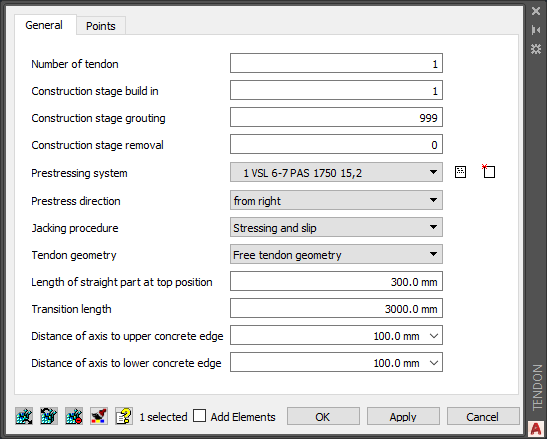
+ The “General” Tab
Besides information about the tendon number and construction stages, you’ll find further input for the actual stressing and most important for the geometry.
- Prestressing System
As mentioned earlier it makes sense to define the prestressing system beforehand, but it can be done from the “Tendon” dialogue box too. By defining the prestressing system, the geometrical boundary conditions – based on the tendon system – will be considered. The default prestressing number is 1. If you haven’t defined a prestressing system yet, create a new one by clicking the most right icon “New…”.
The command “Prestressing Systems” – which can be found in the SOFiPLUS sidebar – opens the dialogue box “SOFiSTiK: Prestressing system” in which you can choose from pre-defined prestressing systems. As not every single prestressing system is implemented in SOFiPLUS, the user-defined system – to select in the “Company” dropdown menu – is a welcome option. - Prestressing Direction
Select from which direction to stress the tendons. Four options are available “the right”, “from left”, “from left, then from right” and “from right, then from left” - Jacking Procedure
Select one of four options for the actual jacking procedure. “Stressing”, “Stressing and Slip”, “Stressing, release and re-stress” and “Stressing, release, restress and slip”.
The following inputs influence the geometry in its elevation. And will also consider the
- Tendon Geometry
- Length of straight part at top position
- Transition Length
- Distance of axis to upper concrete edge
- Distance of axis to lower concrete edge
+ Geometry relevant Inputs
Besides the “High Point” and “Fixed Point” the following parameters are the most important ones for the tendon geometry in elevation.
1 Tendon Geometry
Two options are available to create the tendon geometry in its elevation:
- Free Tendon Geometry
The free tendon geometry is a method to install post-tensioned tendons. The methods name is influenced by the fact, that no supporting elements are required to define the shape. The tendons are connected at the high points with the upper reinforcement at two places and hang completely loosely in between. The tendon lies on the lower reinforcement and is kept in position with a simple wire attachment. At the transition zone from the lower to the upper reinforcement layer, no further support is required. The tendon is usually positioned to the centre of the slab at the anchors.
- Cubic Spline
This option will not force the tendon to remain on the lower reinforcement as it does the “Free Tendon Geometry”. The geometry is defined by piecewise third-order polynomials which pass through a set of control points (“High Points” and “Fixed Points”).
2 High Point and Fixed Point
When using the “Free Tendon Geometry” I recommend using “High Points”. If there is the need to vary from the “Free Tendon Geometry” partly, the “Fixed Point” is a welcome option.
When assigning a “Fixed Point”, the behaviour of the free hanging tendon is interrupted temporarily to the adjacent “High Point”. Also bear in mind, to alternate between “High Point” and “Fixed Point” as assigning two “Fixed Points” in a row will cause a warning. What might not be a problem but needs further investigation to ensure proper working geometry.
The following options are available for the “Free Tendon Geometry only. Selecting the “Cubic Spline” will deactivate them entirely.
3 Length of the straight part at the top position
The input describes the length of the tendon which should be entirely straight. Although the command says, the straight section will be aligned to the top position it works as well for geometry points relative to the bottom edge. The parameter “FRLL” is the related name of the syntax CADiNP (text input method).

4 Transition Length
When it comes to the transition length of the geometry besides the entered value also the minimum radius of the selected “prestressing system” is taken into account. The parameter “FRLT” is the related name of the syntax CADiNP (text input method).
5 The distance of the axis to the upper/lower concrete edge
The Distance between the tendon axis and the edge can be defined for the entire tendon geometry. The entered value will show up in the tab “Points” later. The parameter “ZSPT” and “ZSPB” are the names of the syntax CADiNP (text input method).

+ Context Menu
The “Tendon” dialogue box allows creating a new tendon geometry. You might have already recognised the context menu popping up automatically with the “Tendon” dialogue box. The context menu provides you with options to either convert existing AutoCAD elements to a tendon geometry or to create a new one from scratch.
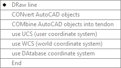
- Draw Line
Creates a linear tendon by selecting a start and end point. - Convert AutoCAD Objects
Creates a tendon out of AutoCAD elements such as lines, splines and arcs. Although polylines can be transferred to tendons – in any case, avoid discontinuities such as kinks. - Combine AutoCAD Objects into Tendon
Creates a tendon from multiple consecutive elements. Again, avoid any discontinuities as it won’t work otherwise.
The next three following options are related to the coordinate system.
- Use UCS (User Coordinate System)
The user can define a new coordinate system. Selection an origin and the directions of the X and Y axis is required. - Use WCS (World Coordinate System)
Switch to the World Coordinate System from AutoCAD. - Use Database Coordinate System
The coordinate system that was defined within the “SOFiSTiK: System Information” dialogue box when starting the project at the very beginning. - End
Closes the option or the command.
To modify a tendon geometry double-click or use the “Modify Tendon Properties” command in the SOFiPLUS sidebar to open the “Tendon” dialogue box again
As SOFiPLUS utilises native AutoCAD commands, tendons can be easily copied, mirrored or moved using the default AutoCAD commands. Manipulating the geometry by using the AutoCAD grips (blue squares when selecting an object) is allowed too.
Creating tendons based on polylines brings a drawback – they can’t be modified in their position afterwards. The end/start points are the only points to be changed in the direction of the tendon’s alignment.
+ The “Points” Tab
The first step of creating a new tendon is to define the geometry in plan view only, what can be done by selecting an existing AutoCAD line or by creating a new one. Settings to specify the elevation of the geometry aren’t available yet (Locked “Points” tab).
The easiest way to add or modify points is to double-click on the tendon geometry or to use the “Modify Tendon Properties” command in the SOFiPLUS sidebar. Both will open the “Tendon” dialogue box again.
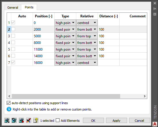
A right-click on one of the cells of the “Position [-]” column opens a context menu with further options such as inserting a new point, select an existing one and delete points
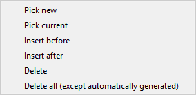
The commands “Pick new”, “Insert before”, “Insert after” and “Delete all (except automatically generated) are always available. If you right-click on a point not created by a support line, the options “Pick current” and “Delete” are offered also.
There is a more comfortable way to create geometry points available – using “Support Lines”.
To take advantage of this feature ensure that the checkbox “auto-detect positions using support lines” is activated.
+ Charting of the Tendon Geometry
Different symbols support you identifying the properties of the geometry points as well as the tendons.
- The hourglass – “High Point”.
- The diamond – “Fixed Point”.
- An arrow represents the direction of the tendon geometry.
- A number to identify each different tendon explicitly.

In some cases, it becomes necessary to invert the direction of the tendon geometry. The command “Invert Tendon” is a useful feature to do that. You’ll find it in the SOFiPLUS sidebar in the “Prestressing” tab.
Define Support Lines
Besides defining geometry points one by one for every single tendon a more efficient way is available. By transforming an existing AutoCAD line or by drawing a new “Support Line” and assigning geometry related information to it you can simplify the processes enormously. As soon as the “Support Line” crosses a tendon – a geometry point will be generated. All properties of the “Support Line” such as type, alignment and distribution are going to be assigned to the generated geometry point.
“Support Lines” make a huge difference in efficiency for a project containing an enormous number of tendons.

The provided dialogue box “Tendon Support line” comes with the following inputs.
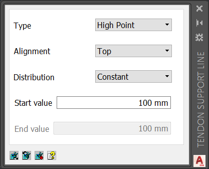
- Type
Either a “High Point” or “Fixed Point” can be selected. - Alignment
The dropdown menu allows to chose the alignment of the geometry related to the slab thickness. The alignment is oriented in the positive local Z-direction of the slab. Three options are available “top”, “centred” and “bottom”. Although “centred” is one of the options, it doesn’t affect. “Centred” is the default option for the start and end of the geometry (done by the software automatically). To create a geometry point precisely at the centre line you can either define only one “High Point” at the start and the end. Alternatively, at an intermediate point – if it is required to temperately run along the centre line – select either “top” or “bottom” and use half of the slab thickness for the start/end value.

- Distribution
Besides the “constant” distribution the “linear” distribution is available. When selecting the latter, bear in mind, the start value is assigned to the start of the “Support Line”, the end value to the end of the “Support Line”.


+ Context Menu
The dialogue box “Tendon Support Line” comes along with a context menu to define “Support Lines”.
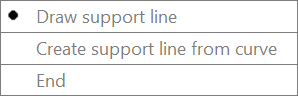
- Draw Support Line
Creates a straight line by selecting a start and end point. - Create Support Line from Curve
Straight lines and splines can be transformed into a support line. - End
Closes the dialogue box command “Tendon Support Line”.
+ Modifying an existing Support Line
Any changes on the geometry of a “Support Line” can be done with native AutoCAD commands. To modify assigned properties – either double-click on the “Support Lint” or use the “Modify support line properties” command in the SOFiPLUS sidebar. Both options open the “Tendon Support Line” dialogue box.
Check the defined Tendon Geometry
For every engineer, it’s essential to have full control at any time of the project. Checking the geometry is, therefore, an important part and can be done in three different applications. Depending on the size and stage of the project the tool most suitable shall be chosen.
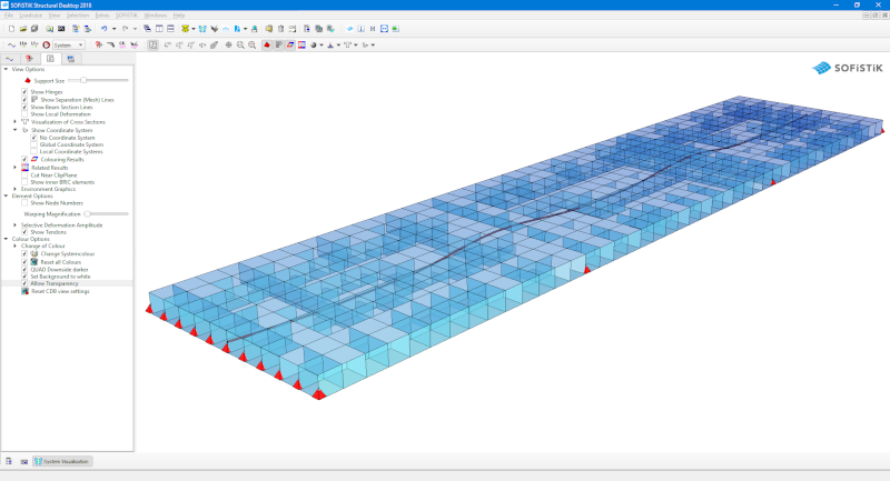
+ System Visualisation
The “System Visualisation” is the quickest way to check the geometry.
Within the application -in the third tab of the sidebar – you’ll find different render options. In the last section “Colour Options” the property “Allow Transparency” can be activated. This setting helps to control elements within the simulated volume of the slab.
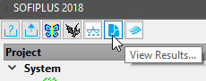
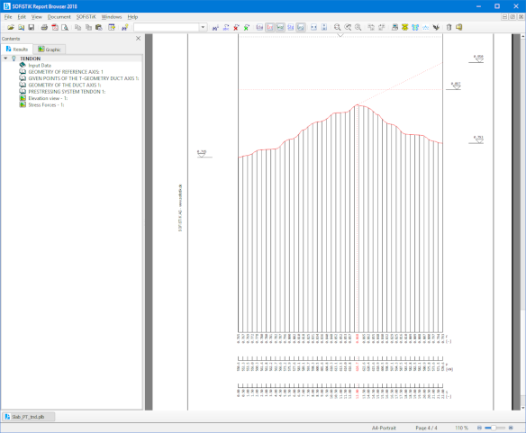
+ Result Browser
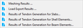
The “Result Browser” represents besides the textual output also a graphical view of the tendon geometry and losses. The report can be accessed from the SOFiPLUS sidebar at the second right command “View Results…”.
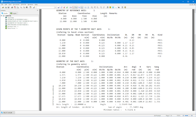
You can also open other reports related to the pre-processing from here. To read the post-tensioning report – select “Results of Tendon Generation for Slabs…”
Textual Output of the given points.
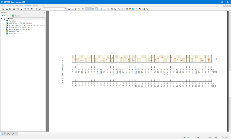
Graphical output of the tendon geometry:
Stress Forces:
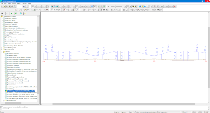
+ SOFiSTiK Graphics / Wingraf
Wingraf allows combining the textual with the graphical results. Within the section “System Values” – in the Wingraf sidebar – you’ll find the sub-section “Quadrilateral Elements” which includes further details of “Tendons”.
Analyse Tendons
Analysis results are required to design the slab. Depending on your intention of the process I’d like to highlight two possible workflows.
If you are interested in the results without any time depended on effects – adding the “Analysis of Slab Prestress” Task in the SOFiSTiK Structural Desktop project tree is sufficient. For a more realistic calculation, I recommend performing a construction stage analysis. It’ll also consider the time-dependent effect such as creep and shrinkage.
Wrap-Up
Defining post-tensioned slabs in SOFiPLUS is smooth and flexible. Manipulating tendons one by one as well as several at a time using support lines – increase efficiency enormously. As the program allows you to access every generated data of the tendons – textual and graphical – checking the input at any time is possible.
Software version: SOFiSTiK FEA v2018-08.
